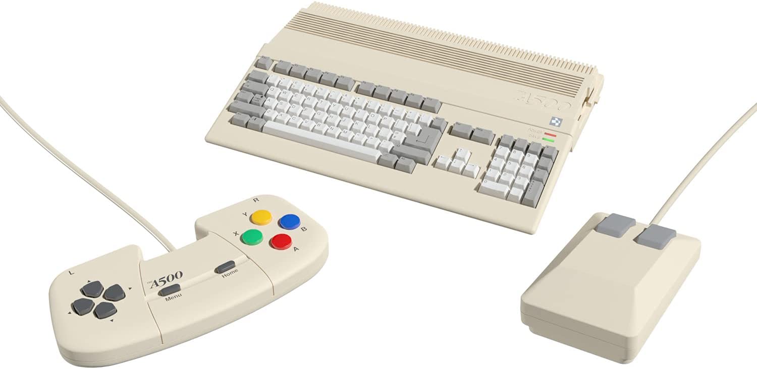
Because a real Amiga 4000 is way to expensive, I bought “The A500 Mini” from RetroGames.
This can be easily modified, to run as an A4000 (with WB 3.1), it can even connect to the internet (via WiFi) with little effort, and a cheap ESP32 module !
(Or use it with other serial hardware, like printers or a null-modem for games …)
(you only need to solder a few wires and modify some the firmware a bit …)
1. Adding a serial connection
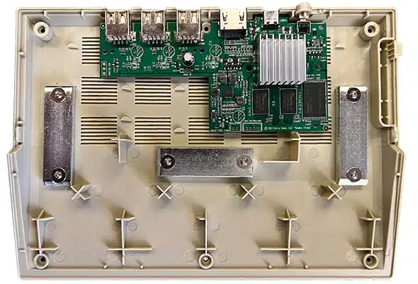
First, unscrew the bottom screws (6). You will then see the mainboard.
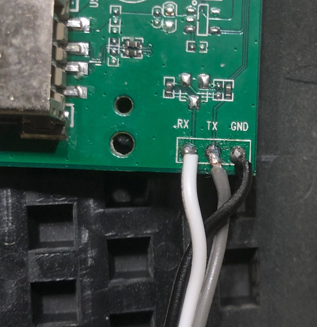
We need to solder a few wires on this board …
When you look to the left side of the board, you will see 3 dots, named RX, TX and GND.
This is actually the first UART port. (there is also another UART port, on the bottom of the board (with 4 pins), but you can’t use this !)
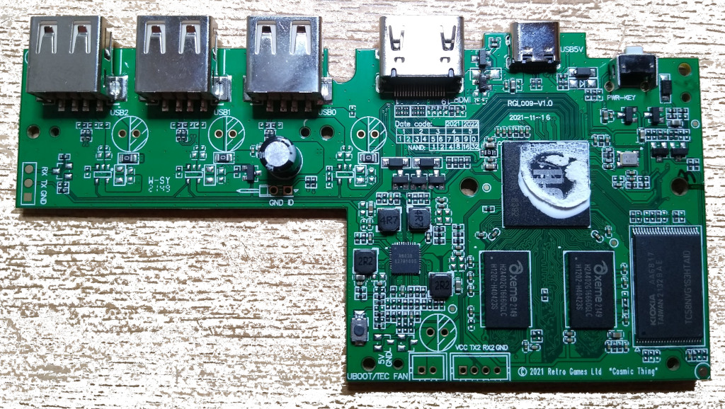
Solder 3 wires to the 3 dots: RX,TX and GND, and connect them to to a USB/Serial adapter. (Set/Use at 3.3V !)
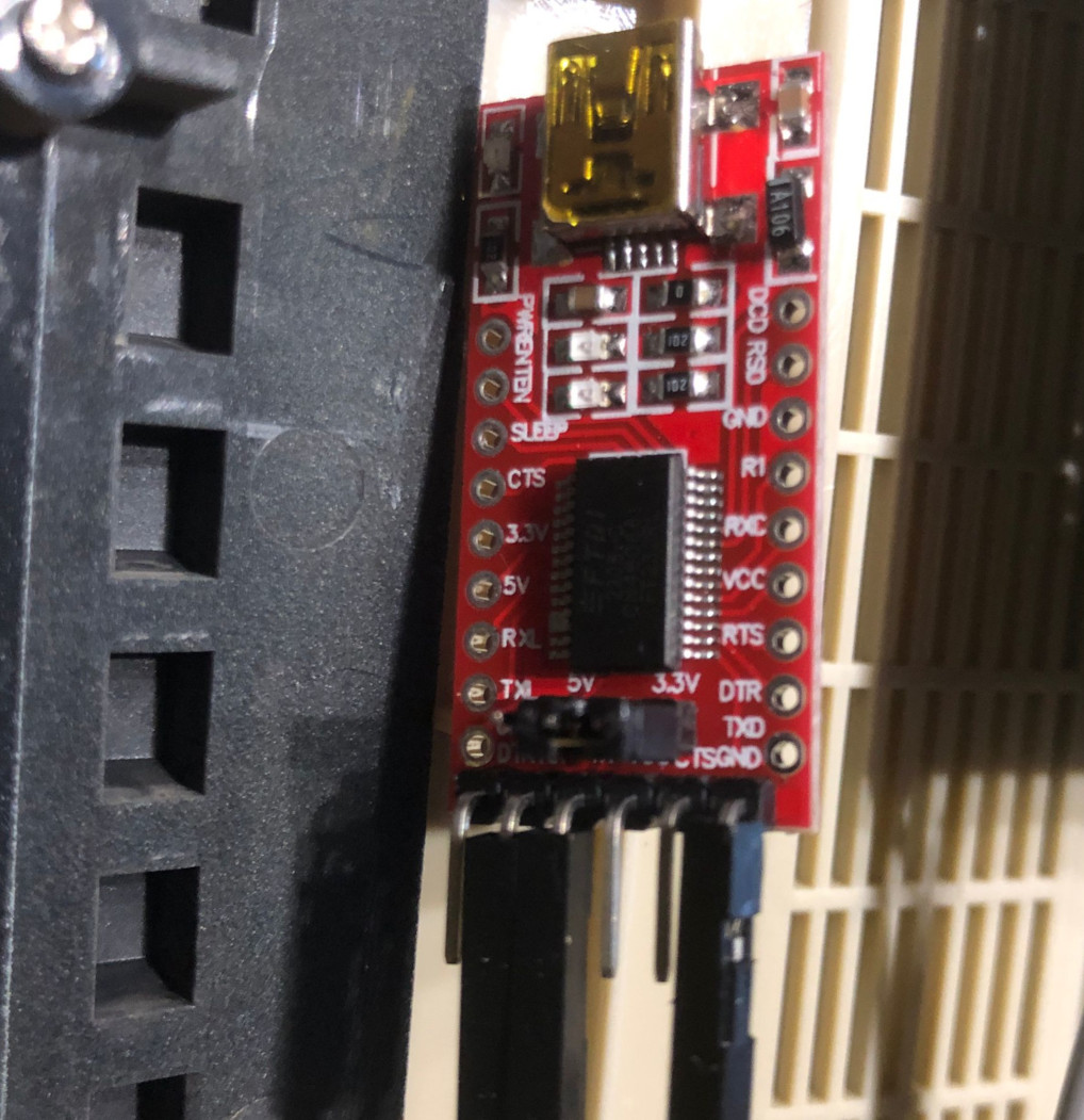
Next, connect the USB/Serial converter to your PC,
make sure the drivers are installed, and start a terminal program. (Putty, which is free, will do fine) Connection settings: 115200/8/N/1 (and no flow control)
When you boot-up your A500 Mini, you should get something like the following picture, in your terminal program.
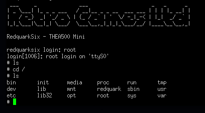
This indicates the connection is OK. You probably will not get any further than the login prompt, because only the folks at RetroGames Ltd. knows the password.
But don’t worry, we will get passed this 🙂
2. Remove firmware password and enable login
– First, update the firmware to the lastest version. Look here to download the latest firmware and how to install it.
– Download the following zip-file, and extract it to a FAT32-formatted USB stick.
– Put the USB stick in the A500 Mini.
– Turn on your terminal software, and hold down the S-key on your computer keyboard, while powering and turning on the A500 mini.
When everything is OK, you will be greeted by a redquark-six# prompt, without the Retro Games Ltd. logo.
– From here on, you need to copy/paste a few commands, line per line, and press <enter> twice, at the end of every line.
(Sometimes, it takes some time for a command to complete, don’t worry !)
usb reset;fatload usb 0 4007f800 A500-nanda-ramfs-enabled
setenv bootargs console=ttyS0,115200 root=/dev/nandb init=/init loglevel=9 mem=512M ramfs
boota 4007f800
mount /dev/sda1 /mnt
insmod /lib/modules/3.10.65/nand.ko
dd if=/mnt/nandb.img of=/dev/nandb
sync
umount /mnt
Reboot your A500 Mini after this, you should then be able to login to after the Retro Games Ltd. logo, with root (and no password).
You now have full access to your A500 Mini 🙂
Next, type killall -STOP sh , this will free the terminal from kernel messages, and allow you to use the UART for other purposes.
When you use a CLI, and type echo test > /dev/ttyS0 on the A500 Mini, this “test” will appear in the terminal on the PC-side.
Whatever you type in the terminal on the PC side, and press enter, that text will appear on the A500 side.
3. Install Pandory 500
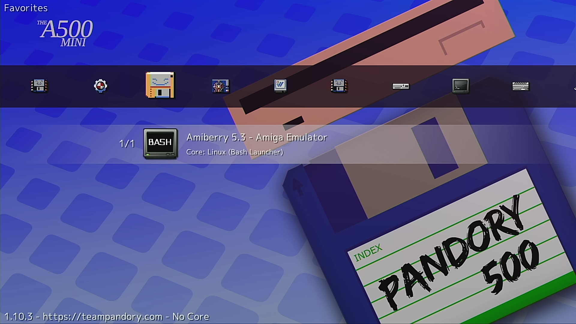
To be able to use the serial connection within AmiBerry (to use the A500 Mini as a real Amiga (4000)), we need to have a more recent version of AmiBerry.
The stock AmiBerry is V3.3+ does not have the possibility to communicate with the UART. Amiberry V5.3 (comes with Pandory500) does !
So, have a look at https://github.com/TeamPandory/pandory500 for downloading Pandory500 and how to install it …
4. Install workbench 3.1 / configure the A500 mini to be an Amiga 4000
First of all, we are going to take a shortcut on this 🙂
There is a great project, called AMINIMiga, which installs Workbench 3.1 and a bunch of software/games, to make your A500 Mini to act like a real Amiga.
Download and install it from here: https://www.aminimiga.com/
Next, try to run this first, from within Pandory500, via AmiBerry 5.3:
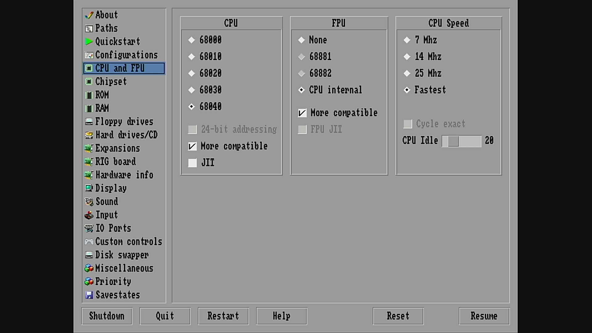
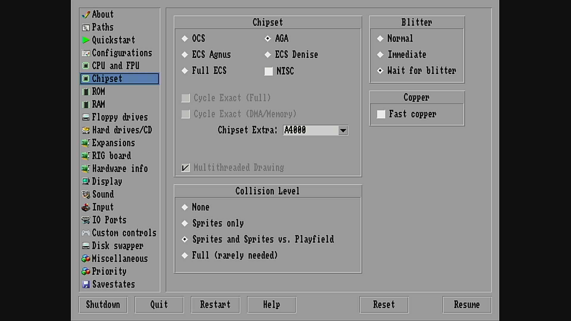
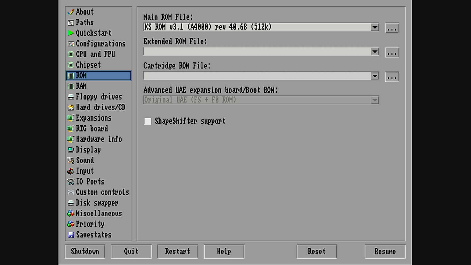
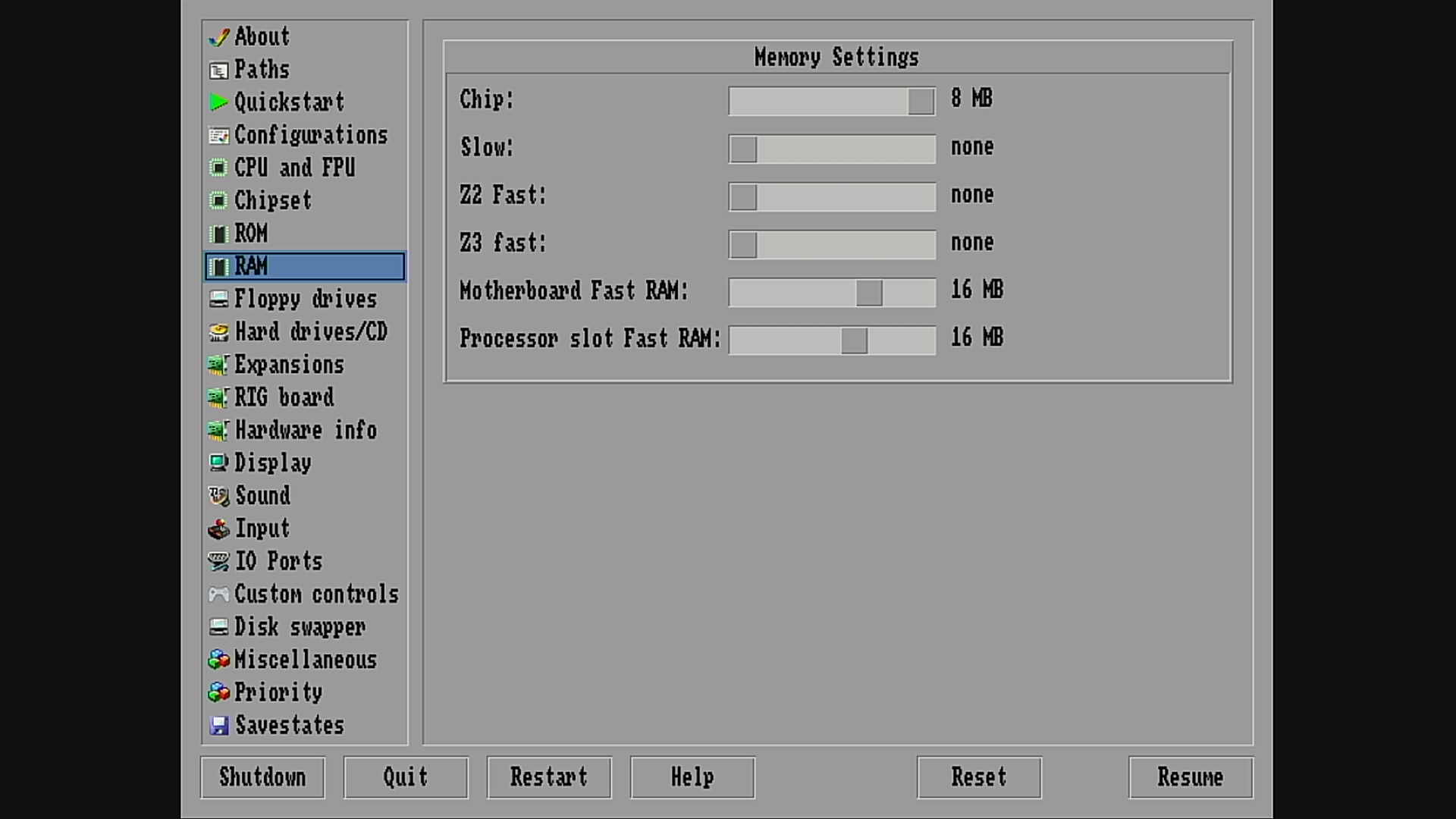
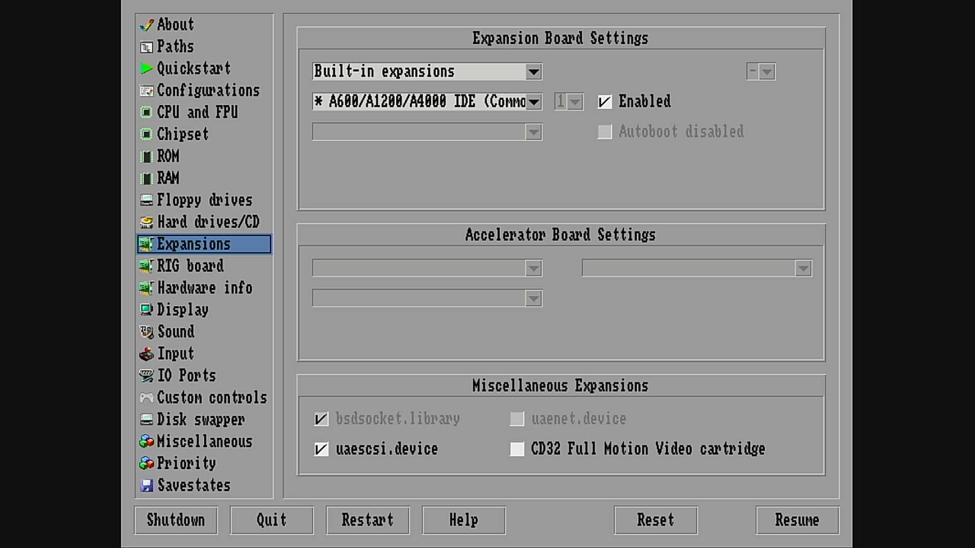
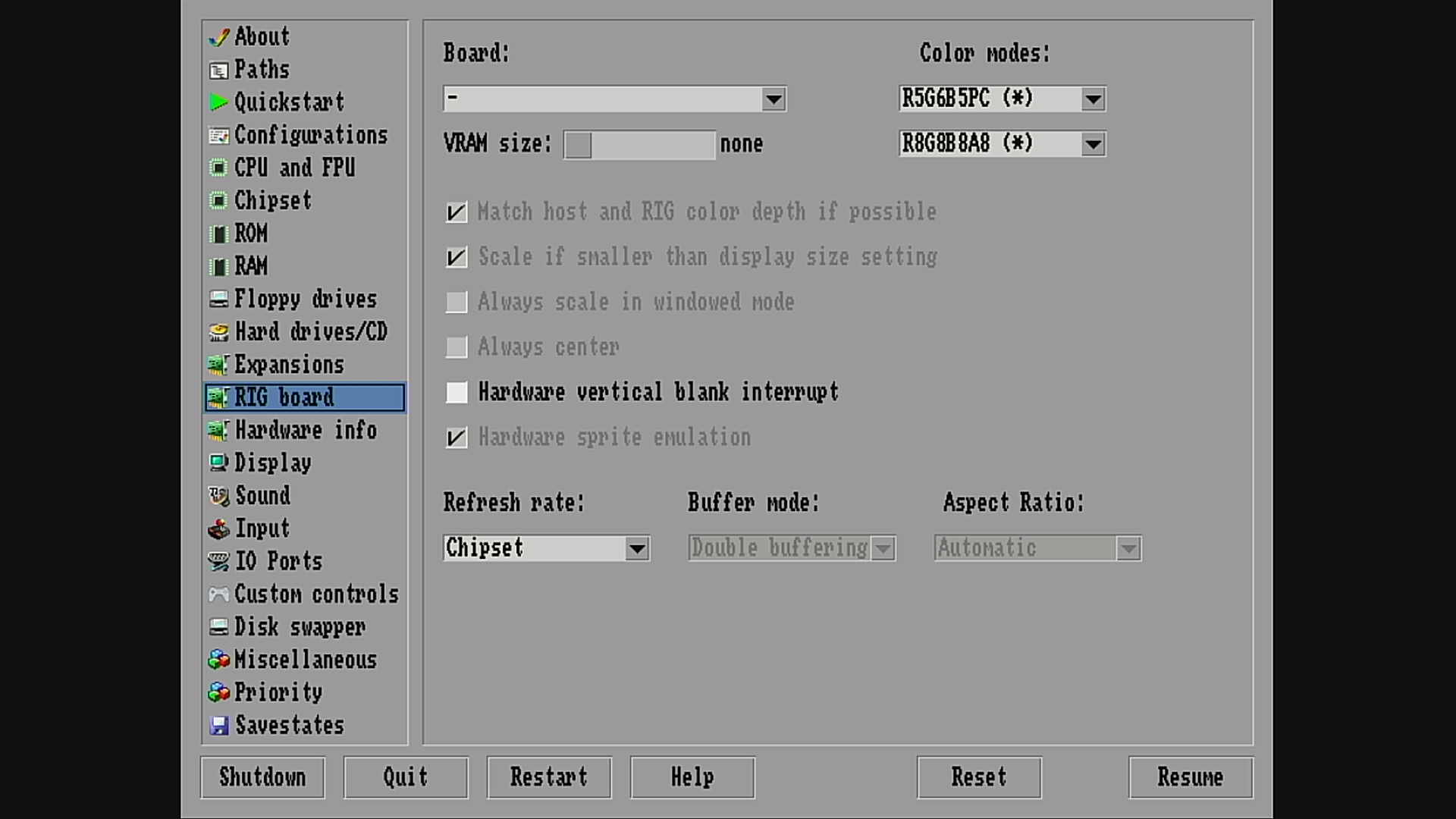
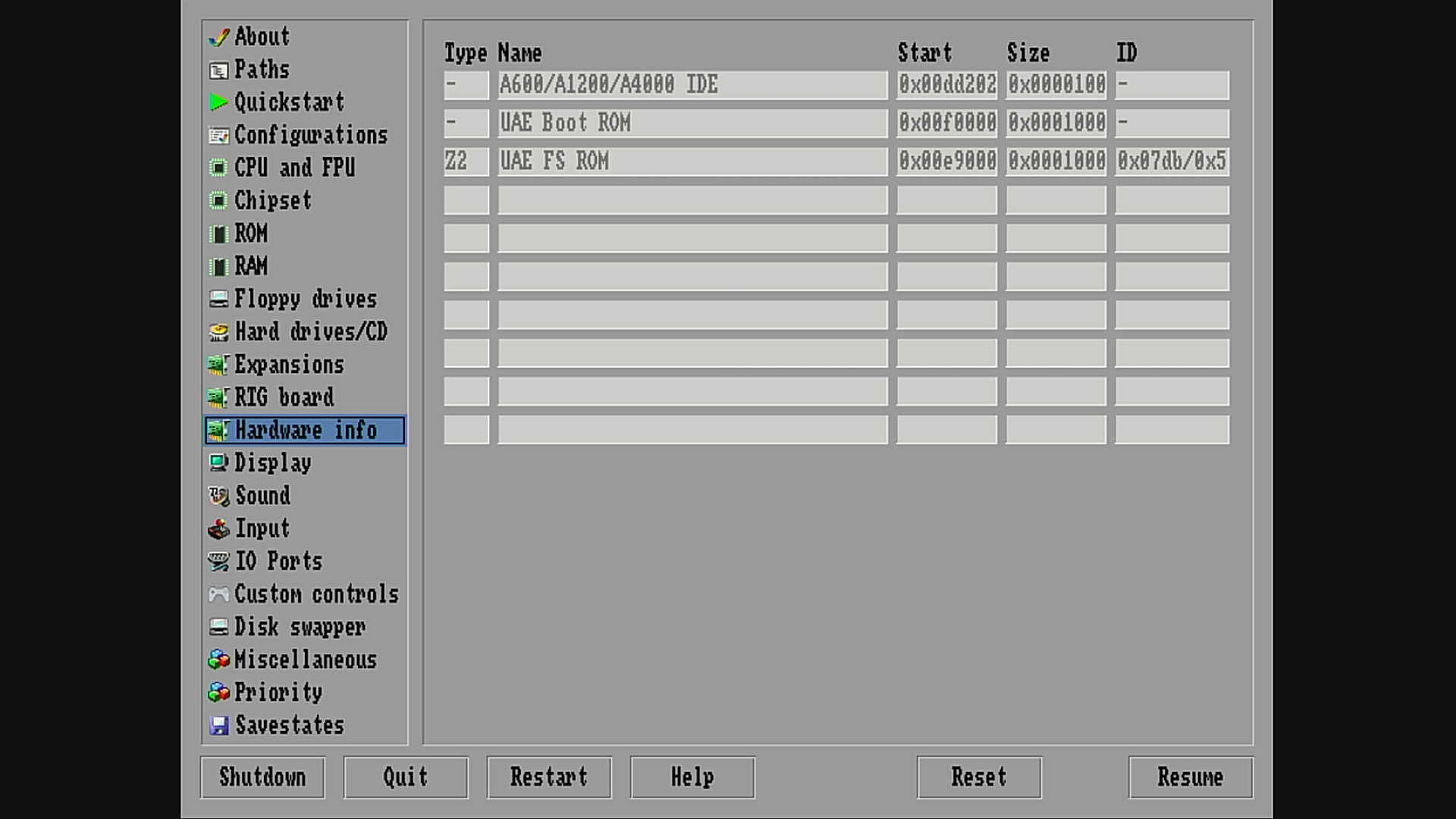
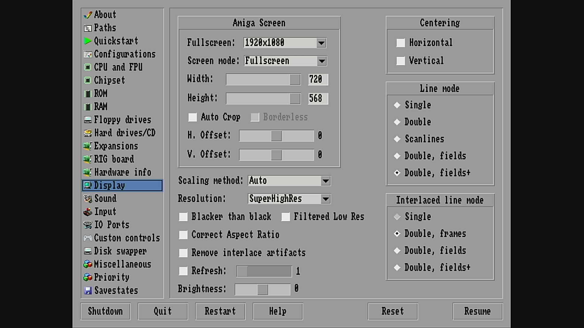
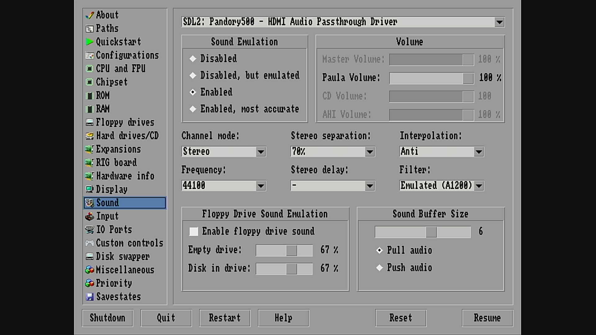
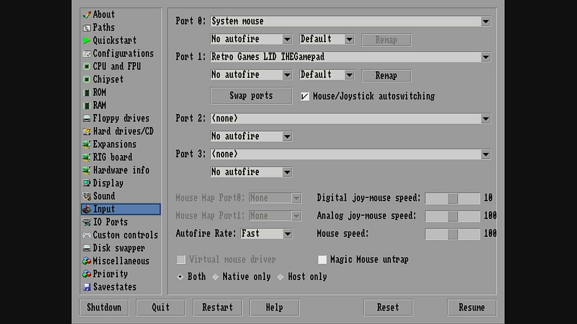
Within the Amiga emulator, press <F12> to get into the AmiBerry config, and make the following changes, to have an Amiga 4000 🙂 (do not forget to save the changes !)
Next time you run the Amiberry emulator (from within Pandory500), you will have an Amiga 4000, with lots of games and software !
5. Use the A500 Mini in “null-modem” configuration
The simplest solution, is to connect one A500 Mini to another A500 Mini.
You only need 3 wires, and a bit of soldering experience 🙂
If you look at the first round picture in step 1, there are 3 wires soldered: RX (White) – TX (Gray) – GND (Black)
At the second A500 Mini, you need to switch RX and TX, so solder the Gray wire to RX, the White to TX, and the black to GND.
That’s all there is, now you have a null-modem connection !
Note that the A500 Mini does NOT support DSR/DTR/RTS/CTS ! So if your software really needs this (which is very unlikely, but you never know), then you are out of luck …
The second solution, connecting an A500 Mini with a real Amiga, is a bit more complicated, and needs an extra (small) module.
The signal-levels at the A500 Mini are 0-3V, which is not a “real” RS232 signal.
So, search on your favorite electronic webshop (amazon/ebay/aliexpress …) for “RS232 Serial Port to TTL Converter”, they mostly come with an onboard MAX232 IC. Make sure you have one that support 3V signal levels. (most do support 3V and 5V, which is fine)
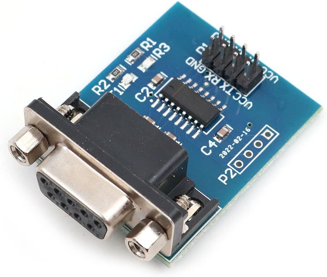
Most of the converters, have a bunch of pins. You only need to connect RX/TX/GND (to the A500 Mini pins), and VCC and GND for power connection. (3V or 5V)
Next, you simply connect a serial cable between this board and your real Amiga, that’s it 🙂
The same note applies as on the null-modem connection, only RX/TX are supported, no DSR/DTR/RTS/CTS !
6. Install software to surf the internet
Before we can surf the internet with our A500 Mini, we need to install some software.
This is nothing else then we did on a real Amiga, when we used a phone-modem to browse the web 🙂
This is the list of software that I used for my combination of A500 Mini and ESP32, so we can use our A500 Mini via Wifi …
7. Install and configure and ESP32 to actually surf the internet via WiFi
We use an ESP32 as a WiFi module. We remove the USB/Serial adapter from step 1, and replace it with an ESP32. You also need the Arduino IDE and some libraries, and my source-code flashed to the ESP32, to make it act like a phone-modem, “translating” this connection to your existing WiFi internet connection …
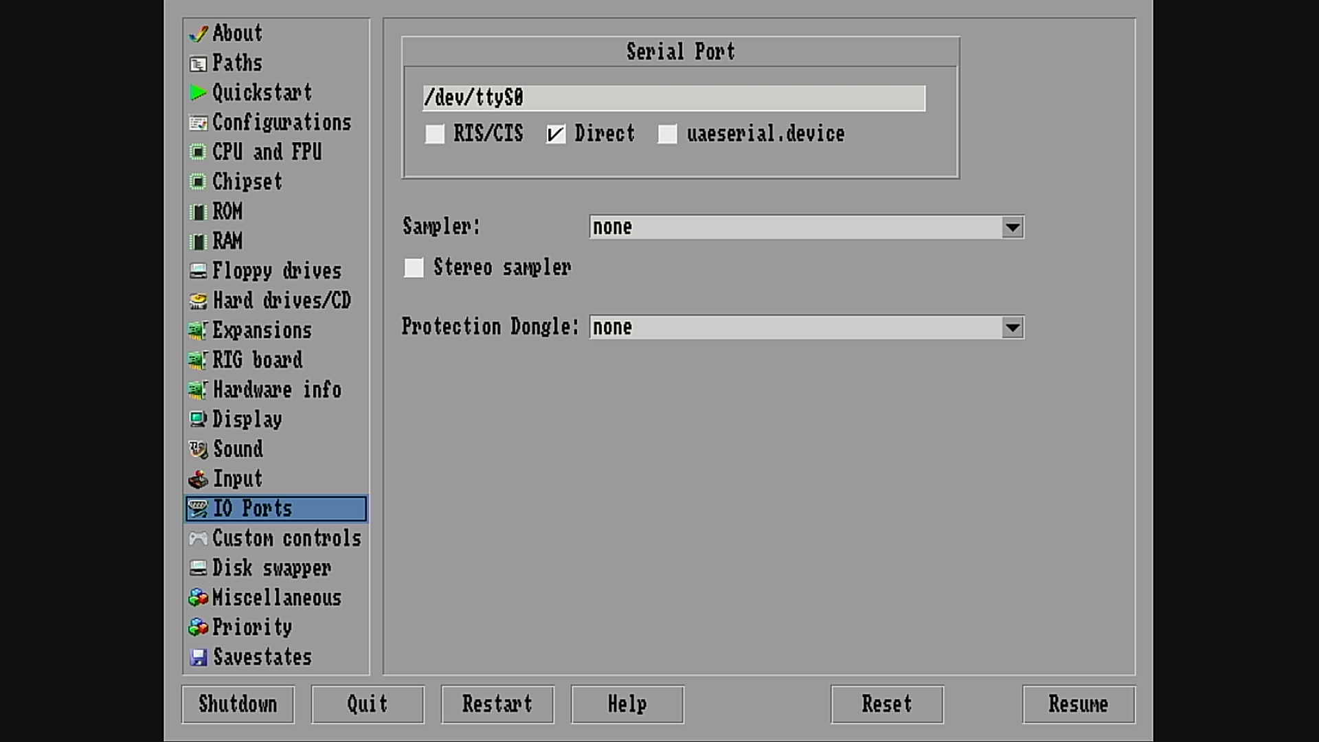
8. Use the serial port from within your own software
Using this serial connection, to connect to your own hardware (or any other serial device), is straightforward. You need the converter from step 5, and voila, you have a “real” RS232 connection on your A500 Mini. (except the DSR/DTR/RTS/CTS signals)
You can “program” it, like you did on a real Amiga, even the portnames etc … are identical.
(and even if you use 115200 baud from the “other side”, it will not go above 37200 baud !)
9. Use a printer
Sorry, but only serial printers are supported. (Until somebody decides to write a USB-to-parallel printerdriver for AmiBerry)
There are 2 distinctive printer-types in the “serial field”.
*One that works via real RS232 connection: I don’t know if this will actually work, I need somebody to test this out, and confirm/deny this to me. Simply use the converted from step 5, and you should be good to go. I assume some printers only use RX/TX, they should work fine. Printers that need more control-signals, will probably not work 🙁
* One that works via TTL signals: I have only seen this type of printer, with only RX/TX connection, no other control-signals needed. However, you should check if your printer supports 3V level signals. If this is the case, you should be good to go. If your printer uses 5V level signals, you need a level converter – TXS0108E. (look on ebay/amazon/aliexpress …)
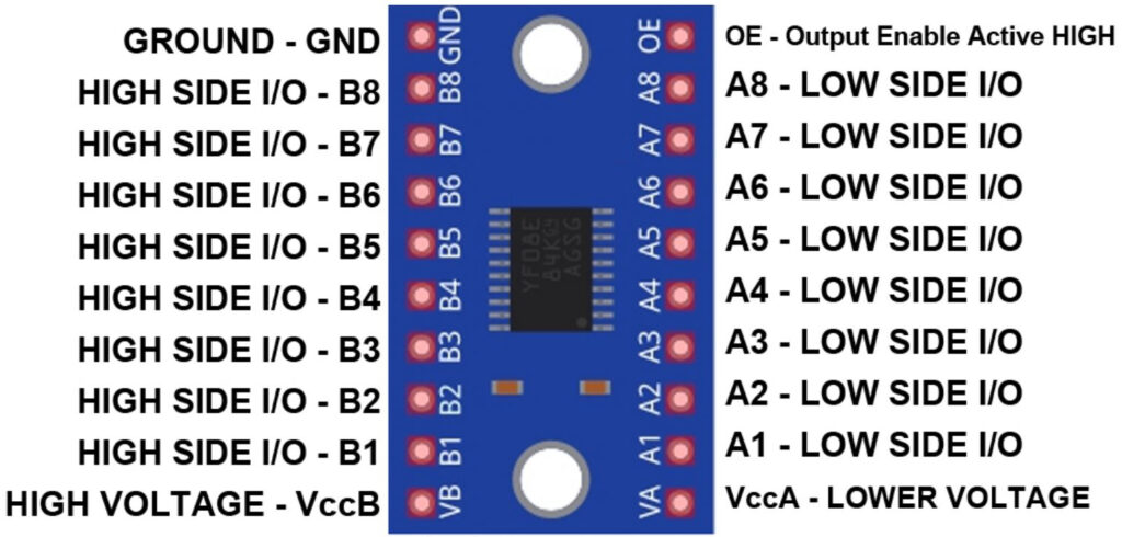
– Connect the RX/TX/GND of the printer, to B1 and B2, GND of the TXS0108E.
– Connect the RX/TX/GND of the A500 Mini to A1,A2, GND of the TXS0108E.
– Connect 3.3V from the A500 Mini to VccA of the TXS0108E.
– Connect GND from the A500 Mini to GND of the TXS0108E.
– Connect 5V from the printer to VccB of the TXS0108E.
– Connect GND from the printer to GND of the TXS0108E.
– Put a 10K resistor between VccA and OE of the TXS0108E.
Note that you will (probably) not find a driver for the Amiga, for this type of printers. (mostly termal printers)
You need to control it in serial mode (plain text, no images) or write your own software to control the printer. (if you want to print images etc …)
Enjoy your A500 mini, now running as an Amiga 4000 with internet connectivity … (or printer or other serial device)